
When specifying components for a hydraulic power unit, the prime mover is sized based on torque, speed, and power requirements of the hydraulic pump. This is fairly straightforward for electric motors because they generally have a starting torque that far exceeds running torque. Often, though, designers specify motors sized larger than necessary. This results in wasted energy because the motor operates at less-than-maximum efficiency.
Diesel and gasoline engines are another matter. They have a much flatter torque-speed curve, so they deliver roughly the same torque at high speed as they do at low speed. This means an internal combustion engine may develop high enough torque to drive a loaded pump, but not enough to accelerate it to operating speed. Consequently, with all other factors being equal, a power unit requiring an electric motor of a given power rating usually requires a gasoline or diesel engine with a power rating more than double that of the electric motor.
Selecting the Optimum Motor Size
The cost of electricity to operate an electric motor over its entire lifespan generally is many times that of the cost of the motor itself. Therefore, sizing the motor correctly for a hydraulic power unit can save a sizable amount of money over the life of the machine. If system pressure and flow are constant, motor sizing simply involves the standard equation:
hp = (Q ×P) ÷ (1,714×EM ), where: hp is horsepower, Q is flow in gpm, P is pressure in psi, and EM is the pump's mechanical efficiency.
However, if the application requires different pressures during different parts of the operating cycle, you often can calculate root mean square (RMS) power and select a smaller, less-expensive motor. Along with the calculation of rms power (Fig. 1), the maximum torque required at the highest pressure level of the application also must be found. Actually, the two calculations are quite simple.
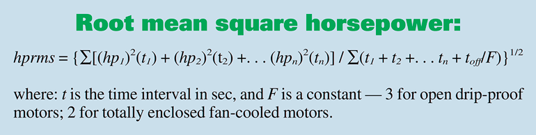 1. Calculation for root mean square power.
For example, such an application might use a 6-gpm, 3,450-rpm gear pump to power a cylinder linkage that operates for an 85-sec cycle (Fig. 2). The system requires 3,000 psi for the first 10 sec, 2,200 psi for the next 30 sec, 1,500 psi for the next 10 sec, and 2,400 psi for the next 10 sec. The pump then coasts at 500 psi for 20 sec, followed by 15 sec with the motor off.
 2. Multiple-pressure duty cycle for 6-gpm gear pump from example with calculated horsepower values.
It’s tempting to use the standard formula, plug in the highest-pressure segment of the cycle, and then calculate:
hp = (6 × 3,000) ÷ (1714 × 0.9)
= 11.7 hp for 10 sec.
To provide this power, some designers would choose a 10-hp motor; others would be ultra-conservative and use a 15-hp motor; a few might take a chance with 7½ hp. These motors in open drip-proof C-face models with feet would carry a relative price of about $900, $1,200, and $600, respectively, so you could save hundreds of dollars per power unit by choosing the 7½-hp motor—if it will do the job.
To determine this, first calculate the power required for each pressure segment of the cycle:
hp1 = (6 × 2,200) ÷ (1,714 × 0.9)
= 8.5 hp for 30 sec.
hp2 = (6 × 1500) ÷ (1,714 × 0.9)
= 5.8 hp for 10 sec. h
p3 = (6 × 500) ÷ (1714 × 0.9)
= 1.9 hp for 30 sec.
The RMS horsepower is calculated by taking the square root of the sum of these power values squared, multiplied by the time interval at that power, and divided by the sum of the times plus the term (toff ÷ F), as indicated in Fig. 1.
Substituting the example values into the boxed equation and solving reveals that hprms = 7.2. Thus, a 7½-hp motor can be used from the standpoint of power alone. However, the second item, maximum torque, still must be checked before reaching a final decision. The maximum torque required to drive this particular pump will be found at the highest pressure—because the gear pump’s output flow is constant. Use this equation:
T = DP ÷ (12 × 6.28 × EM), where T is torque in ft-lb, and D is displacement in in. 3
For this example, D = (6 × 231) ÷ (3,450)
= 0.402 in. 3
Then T = (0.402 × 3,000) ÷ (12 × 6.28 × 0.9)
= 17.8 ft-lb.
Because electric motors running at 3450 rpm generate 1.5 ft-lb/hp, the 17.8 ft-lb of torque requires 11.9 hp (17.8÷1.5) at 3000 psi. This matches closely enough for the example application. (At other standard motor speeds: 1725 rpm generates 3 ft-lb per hp; 1,150 rpm, 4.5 ft-lb per hp; 850 rpm, 6 ft-lb per hp.)
Now the second criteria can be checked against what the suggested motor can deliver in torque. What is the pull-up torque of the 7½-hp motor selected? Because the torque is least as the motor accelerates from 0 to 3450 rpm, it must be above 11.9 ft-lb with an acceptable safety margin. Note that a motor running 10% low on voltage will produce only 81% of rated pull-up torque: in other words, (208÷230)2 = 0.81. Reviewing motor manufacturers’ performance curves will show several available 7½-hp models with higher pull-up torque. Any of these motors could be a good choice for this application.
Both motor criteria now have been verified. The RMS power is equal to or less than the rated motor’s power. The motor’s pull-up torque is greater than the maximum required.
Gas and Diesel Engine Power
Correctly sizing an electric motor for a hydraulic power unit is a straightforward procedure. And if load pressure and flow remain fairly constant, determining the power requirement is relatively simple by using the familiar equation:
hp = (q × p) ÷ (1714 × EM) where: q is flow, gpm (and accounts for the pump’s volumetric efficiency), p is system pressure at full load, psi, and EM is the pump’s mechanical efficiency
For example, assume an application requires a flow of 13.7 gpm at a maximum pressure of 2,000 psi, and with a pump efficiency of 0.80. From the equation above:
hp = (13.7 × 2,000) ÷ (1,714 × 0.80)
= 20 hp.
It may seem that a gas or diesel engine as the prime mover would have the same power rating as an electric motor. However, the general rule of thumb is to specify an internal-combustion engine with a power rating 2½ times that of an equivalent electric motor (Fig. 2). This is due primarily to the fact that internal combustion engines have different torque-speed relationships than electric motors do. Examining the different torque characteristics will provide the understanding to make a choice based on solid reasoning, rather than putting faith in a rule-of-thumb.
Pump Torque Requirements
Power, of course, is the combination of torque and rotational speed. A pump’s torque requirement is the main factor that determines whether a motor or engine is suitable for an application. Speed is less critical, because if a pump runs slowly, it will still pump fluid. However, if the prime mover does not develop enough torque to drive the pump, the pump will not produce any output flow.
To determine the torque required by a hydraulic pump, use the following equation:
T = (p × D ) ÷ (6.28 × 12 × EM) where: T is torque, lb-ft, and D is displacement, in. 3/revolution
Pump displacement is provided in manufacturer’s literature. Continuing with the example introduced at left, if the pump has a displacement of 1.75 in.3/rev., required torque is calculated as follows:
T = (2,000 × 1.75) ÷ (75.36 × 0.80) T = 58 lb-ft
Torque can also be calculated using the familiar horsepower equation:
hp = (T × n) ÷ 5,250 where: n is shaft speed, rpm. Substituting values from the example: 20 = (T × 1,800) ÷ 5250 T. = 58 lb-ft.
Electric Motor Torque Signature
To understand the differences in power characteristics between an electric motor and internal-combustion engine, we'll first examine characteristics of a standard 3-phase electric motor. Figure 3 shows the torque-speed relationship of a 20 hp, 1,800 rpm, NEMA Design B motor. Upon receiving power, the motor develops an initial, locked-rotor torque, and the rotor turns. As the rotor accelerates, torque decreases slightly, then begins to increase as the rotor accelerates beyond about 400 rpm. This dip in the torque curve generally is referred to as the pull-up torque. Torque eventually reaches a maximum value at around 1,500 rpm, which is the motor's break-down torque. As rotor speed increases beyond this point, torque applied to the rotor decreases sharply. This is known as the running torque, which becomes the full-load torque when the motor is running at its rated full-load speed—usually 1,725 or 1,750 rpm.
The torque-speed curve for a 3,600-rpm motor would look almost identical to that of the 1,800-rpm motor. The difference would be that speed values would be doubled, and torque values would be halved.
Common practice is to ensure that torque required from the motor will always be less than breakdown torque. Applying torque equal to or greater than breakdown torque will cause the motor’s speed to drop suddenly and severely, which will tend to stall the motor and most likely burn it out. If the motor is already running, it is possible to momentarily load a motor to near its breakdown torque. But for simplicity of discussion, assume the electric motor is selected based on full-load torque.
Note that Fig. 3 shows a temporary large torque excess that can provide additional muscle to drive the hydraulic pump through momentary load increases. These types of electric motors also can be run indefinitely at their rated hp plus an additional percentage based on their service factor—generally 1.15 to 1.25 (at altitudes to 3,300 ft).
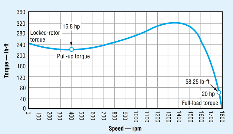 3. The torque-speed curve of an ac electric motor reveals that much higher torque can be generated at low speed than is needed to drive a hydraulic pump at full-load speed. Click on image for larger view.
Catalog ratings for electric motors list their usable power at a rated speed. If the load increases, motor speed will decrease, and torque will increase to a value higher than full-load torque (but less than breakdown torque). So when operating the pump at 1,800 rpm, the electric motor has more than enough torque in reserve to drive the pump.
Torque Signature of Engines
A gasoline engine has a dramatically different torque-speed curve (Fig. 4) than an electric motor does. This means a gasoline engine exhibits a much less variable torque output throughout its speed range. Depending on their design, diesel engines with the same power ratings may generate slightly higher or lower torque at lower speeds than gasoline engines do, but diesels exhibit a similar torque curve throughout their operating speed range.
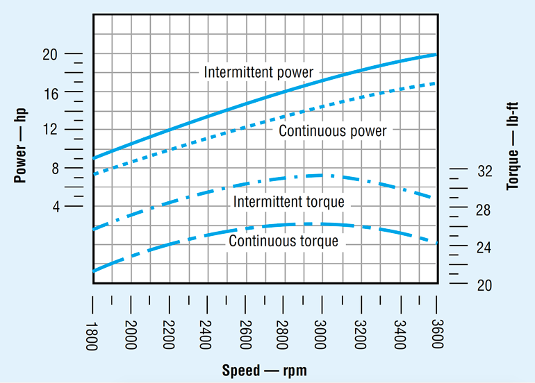 4. The torque-speed curve for an internal combustion engine is much more linear than that for an electric motor. This illustrates that to provide the torque to drive a hydraulic pump at low speeds, gas and diesel engines must have a higher power capacity than an electric motor for driving the same pump.
Calculations above determined that 58 lb-ft of torque is required to drive the pump at any speed. Referring to Fig. 4, the 20-hp gasoline engine develops a maximum torque of only 31 lb-ft—clearly not enough to drive the pump. This is because its 20-hp rating is based on performance at 3,600 rpm. Maximum torque occurs at speeds near 3,000 rpm but is still well below the 58 lb-ft required by the pump. Even if the engine produced enough torque at this speed, power would still be inadequate due to the lower speed.
This is where the 2½ sizing rule comes from. An HPU requiring a 20-hp electric motor to drive the pump at 1,800 rpm would require a gas or diesel engine rated at about 50 hp. Moreover, these values are based on an engine operating at its maximum torque and power ratings. However, manufacturers recommend that gasoline and diesel engines only operate continuously at about 85% of their maximum rated values to prevent seriously shortening of their service lives. So referring again to Fig. 4, a 20-hp gasoline engine would develop just over 26 lb-ft of maximum torque, and only 24 lb-ft at 3,600 rpm.
It is also interesting to compare this performance with fuel consumption. The fuel consumption chart (Fig. 5) shows that a 20-hp gasoline engine achieves greatest fuel efficiency at about 2,400 rpm, where it consumes just over 8.2 lb/hr (0.41 lb/hp × 20 hp). At 3,600 rpm, the engine would be considerably less fuel-efficient.
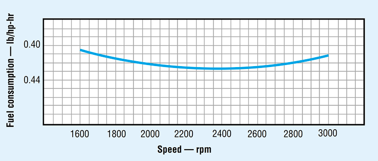 5. Depending on its design, a gas or diesel engine’s optimum fuel efficiency often occurs at a speed other than where it produces maximum torque.
Actions to Take
By now it should be clear that specifying a gasoline or diesel engine to drive a hydraulic power unit follows a different procedure than that for specifying an electric motor. If you are accustomed to specifying electric motors for hydraulic power units, you may be tempted to size a pump to be driven at 1,800 rpm, then specify an oversized motor that can develop enough torque to drive the pump at this speed. This technique will produce a reliable power unit, but one that is relatively heavy, bulky, inefficient, and noisy.
Instead of following this procedure, any of several options should be considered. One would be to drive the pump at a speed higher than 1,800 rpm. Pump literature for mobile equipment should list ratings at a variety of speeds. If it doesn’t, consult the pump manufacturer. Driving the pump at a higher speed decreases its required displacement, thereby reducing its size, weight, and torque requirement. So operating the power unit at higher speed more closely matches engine performance to the application by increasing torque produced by the engine and reducing the torque required by the pump.
More specifically, operating the pump in our example at 2,800 rpm would increase engine torque to more than 30 ft-lb and reduce torque required by the pump to perhaps 38 ft-lb. Although the engine torque still would fall short of that required, it obviously comes much closer to matching pump torque than when operating at 1,800 rpm.
Designers may be tempted to run a gas or diesel engine at or near the speed at which it exhibits optimum fuel efficiency. However, an operating speed where the engine produces maximum torque generally takes priority. This is because if the engine doesn’t generate enough torque at its optimum fuel efficiency speed, a larger engine would be required. But a larger engine consumes more fuel, which would defeat the purpose of trying to conserve fuel by operating at a specific speed.
In addition, pumps generally have a speed range at which they are most efficient. So even if an engine operates a few hundred rpm above or below its optimum fuel efficiency speed, torque produced and pump dynamics generally have a more pronounced effect on overall efficiency of the power unit. Therefore, the speed at which the gas or diesel engine operates should take all of these considerations into account.
As far as pump performance, many designs exhibit higher mechanical and volumetric efficiencies when operated at speeds greater than 1,800 rpm. On the other hand, operating a pump at a speed higher than what it was designed for would reduce its service life. Therefore, it is important to choose a pump speed that offers the best combination of pump and engine performance.
Perhaps an even better alternative would be to provide a gearbox or other type of speed reducer between the engine and pump. Although this would add components to the power unit, it would increase torque and reduce speed while allowing both the engine and the pump to operate at their optimum speeds. The additional cost of the speed reducer may be offset by the lower cost of a smaller, lighter, and less-expensive engine.
Other Considerations
Because gas and diesel engines do not exhibit the torque reserve of electric motors—especially when accelerating from rest—it is especially important that the pump be unloaded whenever the HPU is started. This can be done hydraulically, or mechanically through a centrifugal clutch or other type of drive element.
Finally, as with HPUs driven by electric motors, pump size—and, therefore, size of the prime mover—often can be reduced by incorporating accumulators into the hydraulic system. If the hydraulic system operates in cycles where full flow is needed only for brief periods, an accumulator can store hydraulic power during periods of low flow demand and release this energy when full flow is needed.