
- Home
- About us
- Products
- FC Type Telescopic Cylinders
- FE Type Telescopic Cylinders
- FEE Type Telescopic Cylinders
- Under Body Tipping Cylinders
- Telescopic Cylinders For America market
- 7 Ton and 12 Ton Telescopic Cylinders
- Agricultural Trailer 2 and 3 Stage Tipping Rams
- Dump Trailer Cylinder
- Hydraulic Crutch
- Waste Compactor Hydraulic Cylinder
- Double Acting Telescopic Cylinders
- Bushing Mounting Cylinder
- Clevis Mounting Hydraulic Cylinder
- Snow Plow Hydraulic Cylinders
- Agricultural Hydraulic Cylinders
- Custom Hydraulic cylinder
- Heavy Duty Metallurgical Oil Cylinder
- Engineering Hydraulic Cylinder
- Log Splitter Hydraulic Cylinder
- Tie Rod Hydraulic Cylinder
- Hydraulic Cylinder For Brick Machine
- Agricultural Telescopic Cylinders For Europe market
- Piston Rod
- Cold Drawn and SRB/Hone Tube
- Faqs
- News
- Certificate
- Contact us
Controlling Hydraulic Pressure
time2019/12/23
- Controlling Hydraulic Pressure
Pressure control is achieved in hydraulic systems by metering the flow of a fluid into or out of a constrained volume. Relief valves and pressure-reducing valves are not pressure controllers. They limit or reduce pressure, but they do not really control pressure to a desired value. Pressure-reducing valves can only reduce pressure, and only by a set ratio. The output pressure is limited by the input pressure. Relief valves only limit pressure to a set value. Another limitation of these types of devices is that they use springs and are only proportional-control devices. They have no rate control or ability to change different pressures on the fly.
P-Q (pressure and flow control) valves can regulate either pressure or flow and sometimes flow with a pressure limit. These valves usually have microprocessors or digital signal processors that have a full PID controller inside. P-Q valves are suitable for many pressure-control applications where there is no need to change the pressure quickly or to control a rapidly changing system pressure. The challenge with P-Q valves is that they use a pressure sensor where the flow is high and turbulent.
Also, when oil flows at high speed, the sensed pressure will be low due to the Bernoulli effect. Assuming the sum of kinetic energy, potential energy, and internal energy of a moving fluid remains constant, the Bernoulli effect states that as speed of the fluid increases, its static pressure decreases. Therefore, in dynamic applications, pressure sensors should be mounted where fluid flow is not fast or turbulent.
Some hydraulic motion controllers can also control pressure, force, and position. These controllers have the advantage of diagnostics, control algorithms, and the ability to coordinate many valves at once. This is necessary for applications like hydroforming, where oil pressure will change quickly when compressed or decompressed even a little. In These types of pressure-control applications require rapid response and the ability to meter oil in or out of a compressed volume of oil. Let’s explore some examples.
It’s All About Energy
Adding fluid to a fixed volume increases the pressure, whereas letting fluid out decreases pressure. There is a misconception that pressure is controlled by the pressure gain curve of the valve. This is true only in a testing application, where pressure sensors are connected directly to the A and B ports of the valve. There is no volume of oil under compression.
Another misconception is that “pressure is resistance to flow”. It would be better to say that a resistance to flow will causes a drop in the pressure. Yet another problem is that pressure is related to the internal energy of the fluid. A resistance to flow does not add energy, but it will dissipate energy in the form of heat. Still another widely held misconception is that pumps generate flow, not pressure. Pumps convert electrical energy to mechanical energy, then to hydraulic energy. For a fluid to have energy it must be under pressure, with potential energy due either to elevation or velocity. A pump adds energy to oil in any of the three ways, as described by Bernoulli’s equation:
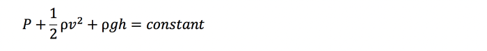
where P is the pressure,
ρ is the density,
v is the velocity,
g is the acceleration due to gravity, and
h is the elevation.
All three terms involve energy. The velocity and gravity term have a density element that makes them an energy density term directly. The pressure still has units of psi, but this can be converted to energy by multiplying by a volume:

Now multiply by a cubic inch:

The unit of pounds force-inch (lbf-in.) are units of energy. These units can also be converted to BTU, which is less inconvenient for us.
Controlling Pressure
Absolute pressure is usually not known exactly. What can be calculated is change in pressure. The basic formula for calculating a change in pressure is:

where ΔP is the change in pressure,
β is the bulk modulus of oil,
ΔV is the change in the volume of oil under compression, and
V is the volume of oil under compression.
Let’s consider a simple example. Assume a single-rod cylinder with no dead volume, and its piston is 10 in. from the cap end. Assume the bulk modulus of oil is 200,000 psi. How much will the pressure increase if the piston is pushed one 0.001 in. (from 10.0 to 9.999 in.) toward the capped end? The answer is the pressure will increase by 20.
If the piston moves another 0.001 in. closer to the end cap, the pressure will increase another 20.002 psi—a total increase of 40.002 psi. This is because the volume of oil is smaller when the piston is moved from 9.999 in. to 9.998 in. from the cap end. Notice that the pressure will increase more and more with every incremental 0.001-in. movement. It is easy to calculate how the pressure will increase as the piston compresses the oil using Excel. Note that the accuracy will increase as the steps become smaller. The exact equation can be derived using calculus.
Pressure doesn’t change in steps in real systems. Pressure changes depend on the rate of volume change or the rate of flow into or out of the volume of oil under compression. This can be expressed by the following differential equation:

where dp/dT is the rate of change in pressure,
Q(t) is the flow into or out of the compressed volume of oil, and
V is the compressed volume of oil. In this example the volume does not change.
It is easy to see the rate of flow into or out of the compressed volume of oil. Now assume the cylinder bore is 4 in., the piston is 10 in. from the capped end, and the rate of flow into the volume is 0.1 in.3/sec.
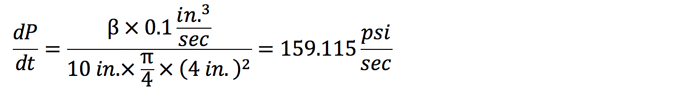
Clearly, it takes very little flow to increase the pressure rapidly.
The force calculation is even simpler:
That is, 2 lb of force per millisecond. The equation for the rate of pressure change is multiplied by the area of the piston, which cancels out the term for the area in the denominator.
The pressure or force normally is controlled when the cylinder is not moving and at the same position each time. This is the case in most press applications. Sometimes pressure or force must be controlled when moving, which is a more complicated situation. In this case, the flow on the pushing side must equal the volume increase created by the moving piston, and the flow out on the opposing side must be equal to the rate at which the volume is decreasing.
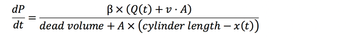
The equation for the rate of pressure change in a moving hydraulic cylinder is:

In this equation, the pressure rate of change on the cap-end of the cylinder is calculated. It is basically the same equation as the previous ones, but the numerator has been expanded to consider the motion of the piston. As the piston rod extends, the pressure will drop unless oil flow is equal to the rate volume change. The denominator also gets bigger as the position increases, resulting in cap-end volume increase.
The rate of change on the rod-side of the piston is similar. When the velocity is positive, the pressure on the rod side will tend to increase unless the flow out is equal to the rate of volume decreased by the motion of the piston:
The pressure on both sides of the piston must be controlled when controlling force. The force is measured using a load cell or using two pressure transducers at either side of the piston. If the latter method is used, the pressure on the cap end is multiplied by the piston area. The pressure on the rod end is multiplied by the piston area minus the rod area and subtracted from the force on the cap side to get the net force.